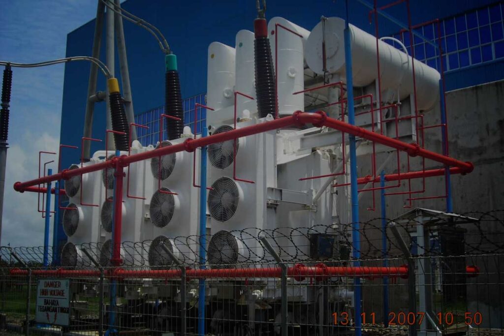
IRC Engineering Services has a vision to diversify its range of services and is committed to provide the best quality and on time services. Their work force comprises of about 20 electrical engineers, having 3 years or more experience in the field of Electrical Testing. They are regularly carrying out testing of HT motors, generators and transformers.
The electrical testing facilities available with IRC are:
- Insulation Resistance and Polarization IndexThe insulation resistance is the quotient of applied voltage across the insulation divided by total resultant current at a given time.Insulation Resistance and Polarization Index of stator winding are measured using a 5 Kv Tera ohm Megger with a constant output of 5000 V DC. IR & PI measurements are taken between each phase and earth while the other two phases are shorted & grounded.
- DC Winding Resistance MeasurementWinding resistance measurements are of fundamental importance for the following purposes:
- Calculations of the I2R component of conductor losses.
- Calculation of winding temperature at the end of a temperature test cycle.
- As a base for assessing possible damage in the field.
Principle:
The basic idea is to inject a DC current through the winding to be measured, and then read the voltage drop across that winding is recorded.
Electrical testing instruments apply Direct Current through the winding and an internal standard current shunt. After both DC voltage drops are measured they are radioed and the display is read as resistance on the front panel meter. This method allows for the lead resistance to be omitted since the reading is independent of the current.
- Electromagnetic Core Imperfection Detection (Digital ELCID) Test The ELCID Test for equipment is conducted to detect faults by exciting the core using a toroidal winding to produce a ring flux similar to the conventional method, but only at 4% of the normal level of excitation. A sensing head is then passed over the surface of the core to detect magnetically the presence of fault currents rather than the heating effect they produce.In the core of the machine is therefore, the circumferential magnetic field due to the excitation, or due to any fault currents present. The effect of the magnetic fields is to produce magnetic potential gradient on the core surface. This magnetic potential gradient is detected by specially wound coil known as Chattock potentiometer, which provides an output proportional to the difference in magnetic potential between its two ends.The sensing head uses a Chattock coil to pick up the magnetic fields. This Chattock coil actually an open-ended search coil, measures the magnetic potential difference between the farther corners of adjacent stator teeth. The Chattock coils output is analyzed by signal processor unit (SPU) and produces a D.C voltage proportional to the fault current component in phase quadrature with the core excitation current. The signal processor is calibrated to give a direct reading of the value of the fault currents as well as Y-axis fault Currents. The SPU also accepts signals from distance encoder providing X axis distance information.
- Tan δ / Power Factor and Capacitance Test Test is carried out on individual phase by disconnecting the station bus from terminals and opening the neutral. Test is performed on stator winding at different voltages. Phase to ground Power factor, Tip Up, Capacitance and Power loss are recorded .Graphs are plotted showing Power Factor Characteristics
- Partial Discharge / Corona / TVA Probe Test The instrument is used with a ferrite probe and is designed to measure negative partial discharge (corona) pulses of widths greater than 20 nanoseconds (ns) having a repetition rate between 20 and 5000 pulses per second (PPS).
Test Procedure:
The test requires disassembling the machine so that there is sufficient access to the air gap to maneuver the probe over the bars or coils in the slot. The winding is energized to normal line to ground voltage with an external high voltage AC power supply. Here one phase is energized while the other two phases are grounded. The probe is positioned against the stator coil wedge so that ferrite rod goes inside the stator by about 100 mm from the slot exit and the readings are taken with the peak pulse meter after energizing the phase winding.
- Wedge Knocking Test It is important to perform periodic checks of the tightness of the stator wedges in the slot.When stator wedges are struck sharply with a hard blunt object the type of sound ( ring ) produced depends upon the tightness of the wedge in the slot. A dull sound indicates a tight wedge; a hallow sound indicates a slack wedge. A ring between these two extremes indicates a wedge on its way to become loose in the future..
- Coupling Resistance between Slot Wall & Bar The measurement of the resistance between the semi conductive coating and the grounded stator core can indicate if the coils are loose in the slot or if the coating has deteriorated. Specifically the semi conductive coating prevents partial discharge (also known as slot discharge) between the coil surface and the stator core. As the semi conductive coating deteriorates, its resistance increases. Also if the coils are loose in the slot, there may be only a few points of contact between the semi conductive coating and core. In both the cases, the contact resistance between the coil surface and core will increase.
Test Proecedure:
The test requires access to the stator winding coils / bars. An electrical contact must be established with a short length of braided wire, making sure that the wire does not come in contact with the core. The resistance is then measured with a standard digital volt-ohm meter between the braided wire and a solid ground point on the stator core.
 IRC Engineering Services