IRC Blog

How Robotic Water Wall Tube Thickness Mapping Saves Electricity Generating Plants from Failures

by sudeep on May 2, 2025

Unplanned outages in power plants are not just minor discomfort – they are financial and operating nightmares. One of the main causes of these unexpected shutdowns is the failure of the boiler water tubes due to Corrosion, deposits, thinning, Hydrogen Damage, etc. If these issues are not addressed to anyone, they can give rise to failures, forcing power plants to close for extensive repair, and losing millions in lost revenue and operational downtime.

But what if we can find out these problems before they become critical? This is where robotic thickness mapping comes in. This advanced non-destructive test (NDT) technique, which is integrated with the robot platform, enables real-time monitoring at early stages of the detection in water wall tubes. This allows power plants to operate active maintenance, avoid expensive breakdowns, and ensure uninterrupted energy production.

Hidden Cost Of Unplanned Outages in Power Generation

Power plants are high-revenue operations that require continuous uptime. Any unplanned shutdown means immediate financial loss, security concerns, and disruption in maintenance.

The financial impact of downtime

  • Unplanned outages are costly: Unexpected plant shutdowns suspend production and require immediate repairs. Unplanned outages cost as much as $2 million an hour, directly impacting operational costs and profitability.
  • Emergency repair is more expensive: Spontaneous equipment breakdown tends to necessitate immediate repair, such as expensive part replacement, overtime compensation, and fixes. These unscheduled maintenance activities are much costlier compared to scheduled maintenance activities.
  • Disruption in energy supply invites punishment: Power plants have to fulfill supply contracts with power grids. Defaulting on the delivery of energy as contracted can lead to substantial financial penalties, damaging both revenues and business relations.
  • Insurance and liability issues: Recurring equipment breakdowns imply inadequate maintenance, which means higher insurance rates and possible legal troubles. This increases operating expenses and subjects the company to more financial and reputational risk.

The Risk of Undetected Corrosion in Water Wall Tubes

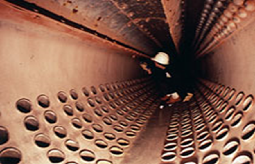
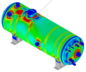
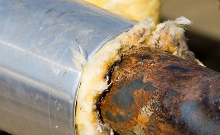
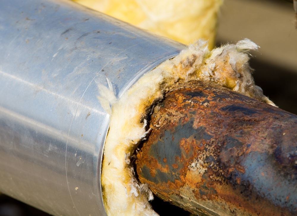
The water wall tubes are brought in contact with high temperatures, high pressure and combustion gases, making them susceptible for rust and thinning.

  • Corrosion weakens the walls of the tube, which increases the risk of rupture and failure.
  • Sudden failure can cause boiler explosions, force emergency shutdowns and workers can cause safety threats.

How Robotic Thickness Mapping Works

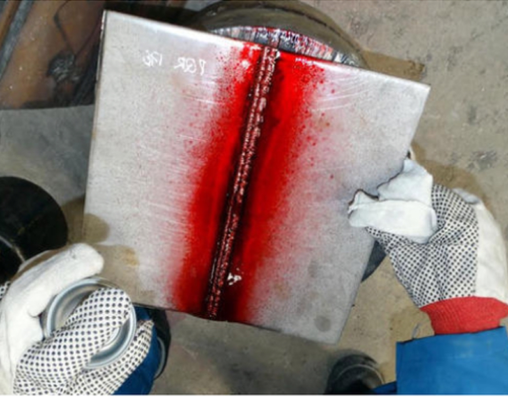
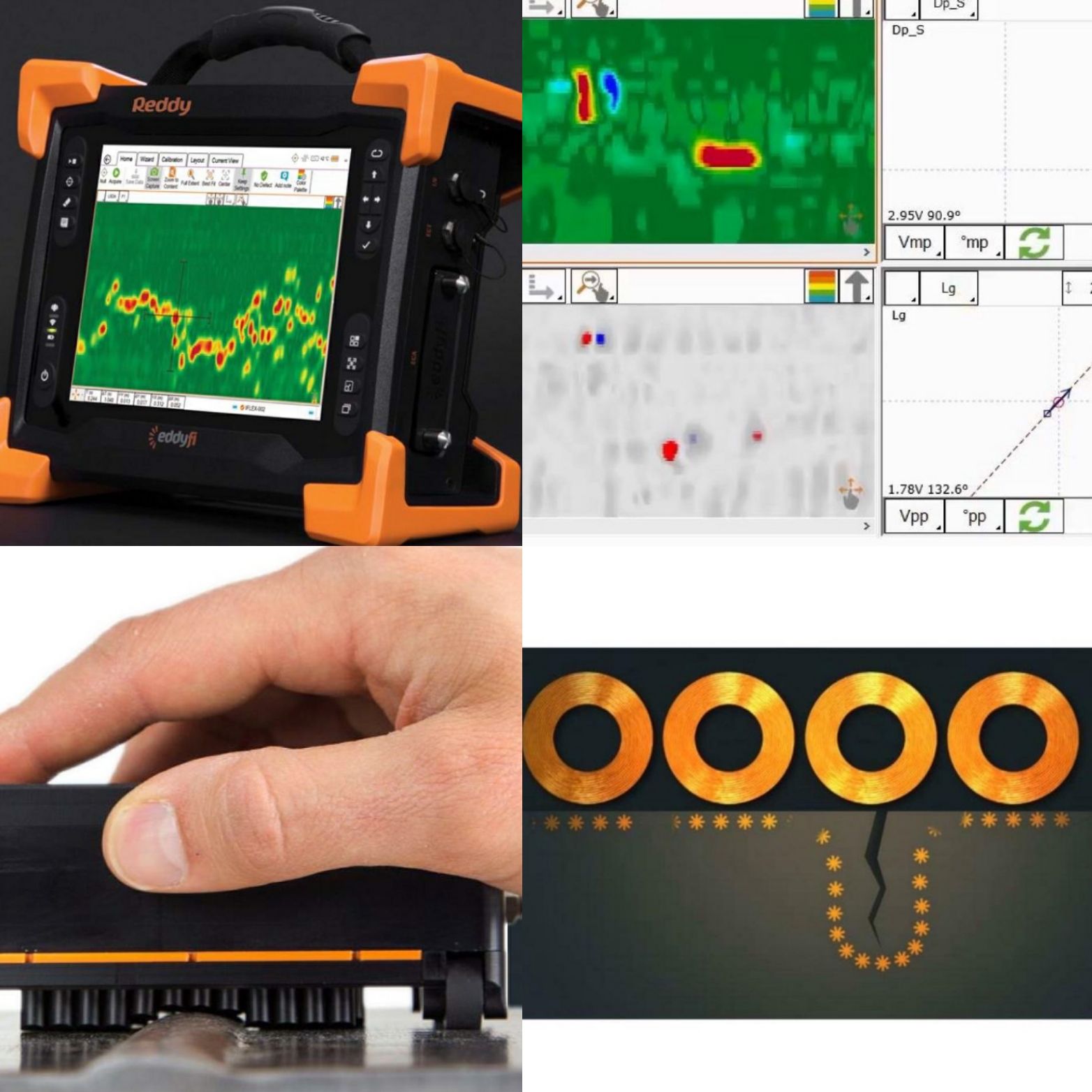
Robotic thickness mapping is a revolutionary non-destructive test (NDT) method that allows engineers to monitor the tube health status without closing the plant.

How it works:

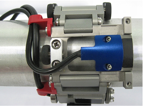
  • Robotic Crawlers: Robots equipped with magnetic wheels and having multiple sensors attached for continuous NDT inspection of tubes
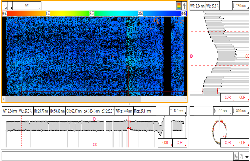
  • NDT Sensor: Various advanced sensors ( RFET, UT) measure the thickness of the wall, corrosion levels, and cracks.
  • Real-time Data Collection: Robot transmission transmits live data, allowing immediate analysis.
  • Predictive Analytics: AI-operated software analyzes historical thickness data to predict potential failures.
  • No Scuffolding is required: unlike traditional inspections, robot mapping is performed, while the plant remains on, avoiding unnecessary downtime.

Example: Robot

  • A magnetic crawler robot that climbs the walls of the vertical boiler eliminates the need for scaffolding.
  • Real-time uses a high-resolution ultrasonic test (UT) to detect a minute thickness variation.
  • Power plants help plan targeted maintenance rather than unnecessary full-scale inspection.

With robotic thickness mapping, power plants can take action before failures, ensuring smooth operation and extended tools.

Limits of Traditional Inspection Methods

Robotic thickness provides rapid, safe, and more accurate inspection than manual methods.

Limits of Traditional Inspections:

  • Time Consuming – Week preparation: Traditional methods of inspection require a lot of setup time, sometimes taking days or even a week. This means creating scaffolding, setting safety gear, and testing areas, resulting in major delays before any work on inspection gets underway.
  • High-risk for workers: Inspectors have to physically ascend high and intricate boiler structures to carry out manual inspections. This subjects them to severe risks like falls, heat stress, and confined spaces, making the work extremely dangerous and accident-prone.
  • Limited accuracy: Manual ultrasonic testing relies considerably on the ability and judgment of the inspector, wherein we are checking the thickness only in localized area rather than mapping the tube , because of which we are highly likely to miss out on defects.

Why robotic inspections are better:

  • 10x faster: Robot inspections significantly cut down on time by scanning enormous areas in no time. Compared to human teams, which could take days, robots accomplish the same task within hours, cutting down on time and reducing downtime, which is important for time-critical industrial processes.
  • Discovers sub-millimeter flaws: Sophisticated robotic sensors are very sensitive and can detect even sub-millimeter thickness variations in material. These small defects usually escape manual inspection but may indicate initial-stage corrosion or damage, enabling preemptive maintenance to avoid larger, more expensive failures.
  • Works in difficult-to-reach areas: Robots are made to reach hard-to-access areas l
  • Protects workers: Robotic inspections eliminate the necessity for human entry into high-risk areas such as high-temperature or toxic environments. This reduces exposure to dangerous conditions, significantly enhancing worker safety and adhering to stringent occupational health and safety guidelines in industries.

Financial Savings To Prevent Detection

Case study: How a power plant saved $ 2M per hour

  • A thermal power plant applied robotic thickness mapping to detect early hydrogen damage in water wall tubes.
  • By changing the damaged tubes before the failure, he avoided a forced shutdown, which could cost $ 2 million per hour.
  • This preventive approach saved millions in emergency repairs and saved expensive punishment.

ROI of robotic inspections

  • Cost of low maintenance – initial identity reduces the requirement for emergency repair.
  • Extended Equipment Life – Active Monitoring prevents premature tube failure.
  • Low insurance premium – Low accidents and failures mean low liability risk.

Frequently Asked Questions

What is the robotic thickness mapping of water wall tubes?

This is an advanced inspection method using a robot system equipped with a non-destructive test (NDT) sensor such as UT/RFET to measure the thickness of water wall tubes and detect early signals of corrosion or damage.

How does robotic thickness mapping stop unplanned outages?

By identifying the initial stage of rust and thinning, robot inspections allow for timely maintenance and reduce the risk of unexpected tube failures and expensive shutdowns.

What are the advantages of robot inspection over manual methods?

Robotic inspections are 10x sharp, sub-millimeters provide accuracy, reduces shutdown duration, maps the entire Boiler Tube rather than in some points only and workers improve safety by reducing dangerous manual inspections.

Which industries benefit from robotic thickness mapping?

Power plants, oil and gas, water utilities, and chemical industries use this technique to expand asset life, improve efficiency, and reduce downtime.

What is the future of robotic thickness mapping?

AI-powered predictive analytics, hybrid robotic systems, and fully autonomous inspection robots will make industrial maintenance smarter, faster, and more cost-effective.

read more
sudeepHow Robotic Water Wall Tube Thickness Mapping Saves Electricity Generating Plants from Failures

How Alternative Current Field Measurement NDT technique can be used in the Inspection of Steel Structures?

by sudeep on May 2, 2025

It is important to ensure the protection and sturdiness of metal systems, particularly in industries that include creation, oil and fuel, and transport. One of the simplest non-destructive testing (NDT) techniques used for inspecting flaws open to the surface in electrically conducting materials.

Alternative Current Field Measurement NDT technique is an advanced electromagnetic technique designed to detect and analyze surface flaws in welds and metal components. It originated in the 1980s, and since then, its accuracy and efficiency have become an industry standard.

The biggest benefit of ACFM on conventional techniques is the capacity to investigate metallic structures without the need to remove the coating. This makes it perfect for assessing bridges, pipelines, offshore systems, and commercial equipment, which guarantees structural integrity by means of lowering downtime.

With its ability to provide real-time defect assessment, ACFM is now used in widely important infrastructure inspections, making it a reliable option to maintain structures worldwide.

Alternative Current Field Measurement NDT Technique Functioning Principles

Understanding how ACFM works helps to appreciate its benefits over traditional NDT methods. The process includes several major stages:

  • Alternative Current Application: An ACFM probe inserts an alternating current into the conducting surface, which travels evenly along the structure when free of defects. The current is vital for the identification of structural integrity, as any fluctuation in flow can identify flaws that are open to the surface.
  • Magnetic Field Generation: As the alternating current passes over the metal surface, it creates a uniform magnetic field around the inspection zone. This magnetic field serves to visualize the state of the metal, thus making it easier to identify anomalies due to material damage.
  • Locating the Disturbances: When the electric current touches a surface breaking flaw, it breaks up the surrounding magnetic field. These field disturbances are signifiers of flaws and their positions. This makes it easier for inspectors to identify cracks without the need to remove coatings or prepare the surface, both saving effort and time.
  • Real-time Data Processing: ACFM software automatically calculates magnetic field perturbations induced by flaws so that inspectors can assess crack size, depth, and severity in real time. Real-time feedback enhances correct decision-making during an inspection, enhancing safety and minimizing repeated testing.

This process makes ACFM a highly effective technique for inspecting electrically conducting structures, as it provides accurate results with minimal surface preparation.

Benefits of Alternative Current Field Measurement on traditional NDT methods

There are many benefits of Alternative Current Field Measurement that distinguish it from traditional NDT techniques:

  • No surface preparation is needed: ACFM can penetrate paint, coatings, and corrosion layers—saving time, labor, and inspection expense considerably.
  • Accurate defect size measurement: ACFM not only identifies surface-breaking cracks but also measures their length and depth with high accuracy, allowing for accurate defect assessment and improved decision-making for maintenance and repair.
  • Data storage digitally: Inspection information is recorded digitally, making it easy to trace, maintain consistent quality checks, and refer to in the future. This facilitates effective documentation, temporal comparison, and adherence to inspection standards.
  • Use in a harsh environment: ACFM operates effectively in harsh environments such as underwater, high temperatures, and in industrial installations, providing continuous inspection without sacrificing safety or equipment performance.
  • Reduced downtime: Because ACFM eliminates surface cleaning or coating removal, inspections are faster, reducing equipment downtime and production losses while providing thorough flaw detection.

These benefits make Alternative Current Field Measurement an ideal option for industries where security and efficiency are paramount.

Major Application of Alternative Current Field Measurement in Steel Structure Inspections

Alternative Current Field Measurement is widely used in various industries to inspect steel structures, including:

  • Bridge and Highway – Alternative Current Field Measurement is used to detect weld defects in important areas of joint bridges and highways. This helps prevent structural failures and ensures long-term durability.
  • Offshore oil and gas platforms – technology is ideal for removing protective coatings, reducing downtime, and inspecting welds while improving safety in a rigid sea environment.
  • Pipelines: Ensuring safe operation by detecting the cracks that break the surface in power plants and pipelines-pipelines, reactors, and pressure vessels, which helps prevent expensive leaks and failures.
  • Industrial machinery and crane – Alternative Current Field Measurement plays an important role in preventing mechanical failures by identifying hidden defects in structural components, which ensures smooth and safe operations.
  • Amusement Park ride – Regular inspections using Alternative Current Field Measurements help to ensure ride safety by monitoring steel components that undergo high stress and fatigue.

The versatility of the Alternative Current Field Measurement makes it a valuable tool to ensure the structural integrity of significant steel infrastructure.

Case Studies on ACFM

Examples of the real world demonstrate the effectiveness of ACFM:

  • Bridge Inspection – In a recent inspection of a major highway bridge, ACFM discovered any kind of crack in critical weld joints. By early identifying these defects, engineers were able to maintain preventive maintenance to avoid potential structural failure and expensive repairs.
  • Offshore platform safety – An oil and gas company used ACFM to inspect Sabasia Welds on the offshore platform. Technology successfully identified fatigue cracks which were hidden under protective coatings. This discovery prevented a possible security threat and saved millions in repair cost to the company.
  • Manufacturing Industry – A Steel Fabrication Plant applied ACFM as part of its quality assurance process. The technology helped identify the early welding defects in the production line, reduced the rejection rate and improved the overall product reliability. This increased efficiency and much less material wastage.

These case studies highlight why ACFM is preferred in industries where structural security and cost efficiency are top priorities.

Challenges and limitations of ACFM

While ACFM is a powerful tool, it has some limitations:

  • Efficient operators are required – ACFM data interpretation requires trained professionals who can make accurate analyses of signals and detect discrepancies. Without expertise, the results can be misrepresented, causing incorrect assessment.
  • Limited to surface defects -ACFM is highly effective for detecting surface flaws, but it cannot identify deep, sub-destiny flaws within the material. Other NDT techniques, such as ultrasonic testing, may be required to detect internal defects.
  • High initial cost – ACFM equipment is more expensive than traditional NDT methods such as magnetic particle inspection or dye penetration test. However, its long -term benefits, such as downtime, low and high accuracy, can offset the initial investment.
  • Magnetic noise sensitivity – The accuracy of ACFM reading can sometimes be affected by external electromagnetic fields. It can introduce noise in data, making it more challenging to inspect the atmosphere with high electromagnetic interferenceintervention.
  • Complex geometrical accuracy can affect accuracy – ACFM works best on relatively flat or simple structures, but when inspecting complex geometrics with many angles and welds, the signal may not be as clear. Such cases may require special investigation and adjustment.

Regardless of these limitations, ACFM is a highly effective way to detect surface flaws in steel structures. Its benefits in speed, accuracy, and non-intrusive inspection make it a favorite option for important industries.

Future Trends in ACFM Technology

The future of ACFM technology seems to be promising, with many progresses on the horizon:

  • Integration with Robotics: Robotic ACFM inspection automatically allows for safer operations through reduced human exposure to harmful environments, providing consistent and accurate assessments even in inaccessible or hazardous inspection areas.
  • AI and Machine Learning Improvements: Artificial Intelligence in ACFM enhances defect detection and interpretation, allowing for quicker, more accurate analysis, minimizing human error, and simplifying decision-making in non-destructive testing (NDT) procedures.
  • Wireless and Portable ACFM Devices: Portable, cordless ACFM equipment expands mobility and convenience in the field, streamlining inspections in confined or inaccessible locations without requiring heavy machinery. 
  • Increased Material Compatibility: Continued research seeks to develop ACFM for use on more materials and complicated geometries, expanding its ability to work efficiently across a variety of industries and improve structural safety analysis.
  • Cloud-Based Data Storage: Cloud-stored digital ACFM inspection data provides secure, real-time access, simplified collaboration, long-term storage, and analysis of data from anywhere, enhancing traceability and efficiency.

This progress will make ACFM more efficient, accessible, and reliable for future steel structure inspections.

Conclusion

The alternative current field measurement (ACFM) has revolutionized the way steel structures are inspected. With its high accuracy, minimal surface preparation, and real-time data processing, ACFM has proved to be a game-changer in industries such as power generation, oil and gas, and transport. While challenges remain, the progress in technology is making ACFM more effective than ever. Since industries prioritize safety and efficiency, ACFM will be an important tool to ensure long the -term integrity of steel infrastructure.

Frequently Asked Questions

What is ACFM in NDT?

Alternative Current Region Measurement (ACFM) is an advanced electromagnetic NDT technique used to detect and analyze surface-flaws in electrically conducting materials.

How is ACFM different from other NDT methods?

Unlike traditional methods, ACFM can inspect through coatings, provides real -time digital data, and accurately measures the defect shape without the need for surface preparation.

Where is ACFM usually used?

ACFM is used to ensure wide structural integrity in bridges, offshore oil platforms, pipelines, industrial machinery, and amusement park rides, and to prevent failures.

What are the limits of ACFM?

ACFM requires trained operators, is limited to surface defects, has high early costs, and can be affected by magnetic noise in complex geometry.

What is the future of ACFM technology?

Progress such as AI integration, robotics, portable devices, and cloud-based data storage will increase the efficiency and access of ACFM in the future.

read more
sudeepHow Alternative Current Field Measurement NDT technique can be used in the Inspection of Steel Structures?

Revolutionizing Industrial Inspection with InspectO: Your Ultimate Asset Management Solution

by sudeep on April 26, 2025

In today’s fast-paced industrial landscape, the efficient management of assets is crucial across various sectors such as power plants, oil and gas refineries, petrochemical facilities, and offshore platforms. Traditional methods relying on manual records and fragmented processes are no longer sustainable. Enter InspectO, a cutting-edge Inspection Data Management System (IDMS) by IRC Engineering Services.

Digital Transformation for NDT Industries

InspectO is designed to streamline and enhance the inspection process for critical industrial assets like piping systems, heat exchangers, boilers, storage tanks, and more. It integrates seamlessly with ERP solutions, offering a comprehensive suite of features tailored to meet the unique needs of asset-intensive industries.

Key Features of InspectO

  • Centralized Digital Asset Register: Consolidate all asset details into a single, accessible repository, eliminating the need for scattered documentation.
  • Comprehensive Data Management: Store and manage documents, drawings, and asset specifications with ease, ensuring quick retrieval and updates.
  • Historical Data Access: Access detailed historical inspection data effortlessly, empowering informed decision-making and compliance tracking.
  • Automated Inspection Scheduling: Never miss an inspection with automated scheduling and reminders, optimizing asset uptime and regulatory compliance.
  • Mobile & Offline Access: Enable field inspectors to log data in remote locations without connectivity, ensuring data integrity and continuity.
  • Custom Dashboards & Real-Time Analytics: Gain actionable insights into asset health and performance with customizable dashboards and real-time analytics.

Empowering Industries with InspectO

1. Enhanced Efficiency: InspectO digitizes and automates the inspection workflow, reducing manual errors and streamlining operations.

2. Improved Compliance: Ensure adherence to regulatory standards with accurate, centralized inspection records and compliance management.

3. Enhanced Safety and Reliability: Proactively manage asset health with real-time monitoring and predictive maintenance capabilities.

Use Cases in Diverse Industries

InspectO caters to a wide range of industrial applications, including:

  • Oil and Gas Refineries: Manage complex equipment like columns, towers, and reboilers with precision.
  • Power Plants: Ensure the reliability of boilers, condensers, and turbines with systematic inspection and maintenance.
  • Petrochemical Facilities: Monitor critical components such as scrubbers, reactors, and separators for optimal performance.
  • Offshore Platforms: Streamline inspections for platforms, vessels, and underwater structures with mobile accessibility and 3D visualization capabilities.

Inspection Made Smarter with 3D Visualization

InspectO leverages advanced 3D visualization tools for AUT data, enabling detailed analysis and reporting of inspections. From detecting flaws in pressure vessels to assessing corrosion in storage tanks, InspectO ensures thorough asset management with visual clarity and precision.

Conclusion

InspectO from IRC Engineering Services revolutionizes industrial inspection and asset management, paving the way for digital transformation in asset-intensive industries. By integrating cutting-edge technology with robust functionality, InspectO empowers industries to achieve operational excellence, compliance, and asset longevity.

Explore how InspectO can transform your asset management practices and propel your business into the digital age. Contact IRC Engineering Services today to schedule a demo and discover the future of industrial inspection with InspectO.

read more
sudeepRevolutionizing Industrial Inspection with InspectO: Your Ultimate Asset Management Solution

IRC Engineering Services India Pvt. Ltd. is the fastest growing Testing, Inspection, Training & Certification Company in India & Globally.

by ircengg on March 12, 2022

IRC Engineering Provides Conventional NDT, Advanced Non-Destructive Testing (ANDT), Material Testing (Metal, Chemical & Corrosion), Mechanical Integrity, Rope Access, Drone Inspection, Third Party Inspection (TPI) Services for the Inspection of Companies assets like Tank, Vessel, Pipeline, Tubes, Boiler RLA and many more.

We have introduced advanced NDT Technology Short Range Ultrasonic Testing (SRUT) a unique ultrasonic screening tool designed to detect Corrosion/ Inspect difficult to access locations such as

· Underneath Saddle Supports

· Under clamps

· Under composite repairs

· The annular plate of above-ground storage tanks (In-Service)

· Pipe to soil interface areas

· Pipe to Cement interfaces

How It Works: The technique is based on the concept of pulsing guided laminar waves into the base material from the accessible area (chime/pipe support surrounding areas). The waves propagate up to two meters into the plate/pipe. When corrosion, pitting, erosion are present the ultrasonic waves mode convert and are received by the same transducer.

Application Pictures;

For More Information please send us an e-mail at info@ircengg.co.in

read more
ircenggIRC Engineering Services India Pvt. Ltd. is the fastest growing Testing, Inspection, Training & Certification Company in India & Globally.

Inspection of Boiler Bank Tubes | Internal Rotary Inspection System (IRIS)

by ircengg on May 28, 2021

Are you unable to carry out the Inspection of Boiler Bank tubes?

Are you regularly carrying out Capital Investment by purchasing tubes rather than finding only the defective Bank Tubes?

Here is the solution for inspection of Boiler Bank Tubes –

In case of Boiler Bank Tubes, only the Front Column of Tubes are available for Inspection for Thickness Testing externally there is no other way to check the rest of the Tubes. Thus we have only 5 % of the Tubes available while we miss out on an inspection of the rest of the 95% of the tubes.

RFET was done previously to ascertain the condition of the rest of the 95% of the tubes but due to the limitation of the technique it is also not a right testing method. Then we tried IRIS on these tubes and got amazing results.

HOW IT WORKS –     

Because IRIS is an ultrasonic technique, it requires a couplant. In this case, water. Tubes under test must therefore first be flooded to use this technique. IRIS relies on a transducer to generate an ultrasonic pulse parallel to the axis of the tube under test. It also relies on a rotating mirror that directs the ultrasonic wave into the tube wall.

The mirror is driven by a small turbine powered by the pressure of water pumped into the tube. Part of the ultrasonic wave is reflected by the inner diameter (ID) wall, while the rest is reflected by the outer diameter (OD) wall of the tube. Because the ultrasonic velocity of the tube’s material is known, it is possible to assess the thickness of the wall by calculating the difference in times of flight between the two diameters. As the probe is pulled, the spinning motion of the mirror results in a helical scan path.

A critical aspect of IRIS is ensuring that the mirror is at the centre of the tube. An off-centre ultrasonic pulse yields a distorted scan image because of the different ID and OD wall sound paths. That’s why our IRIS kits are equipped with centring devices helping operators keep the system centred.

About IRC Engineering Pvt. Ltd.

IRC is one of the fastest growing Testing and Inspection company in India. We at IRC provide Liquid Penetrant TestingNon-Destructive Testing, Destructive Testing, Advanced NDT, Third Party Inspection, Condenser Testing, Electrical Testing, Residual Life Assessment of Power Plant, O&M Services, Fitness For Service, Civil Testing and Training services.

read more
ircenggInspection of Boiler Bank Tubes | Internal Rotary Inspection System (IRIS)

Liquid Penetrant Testing – Advantages, Disadvantages & Alternatives

by ircengg on January 5, 2019

Out of all the non-destructive testing techniques, only a few are suited for every type of application. For instance, on most composite materials, electromagnetic testing techniques don’t work, while computed tomography and X-rays are ideal. Likewise, ultrasounds are adaptable, but require appropriate coupling and direct contact with the surface under test, which is not possible in all cases.

What’s Liquid Penetrant Testing? 

Liquid penetrant testing, also known as dye penetrant inspection (DPI) or liquid penetrant inspection (LPI) is one of the most common and affordable solution and one of the oldest, if compared to non-destructive testing challenges. 

The method leverages capillary action, i.e, the ability of a liquid to flow into narrow spaces without help, even in opposition to, external forces such as gravity—to detect surface-breaking defects.

The excess is removed and a developer is applied after applying the penetrant and letting it dwell for a certain period. From surface-breaking defects, the developer draws the penetrant where it’s seeped, revealing their presence.

Advantages of LPI

Liquid penetrant testing has the following advantages:

  • Works on complicated geometric shapes
  • LPI materials are compact
  • Sensitive to small surface interruptions
  • Few material limitations such as—works on non-metallic, metallic, non-magnetic, magnetic, non-conductive and conductive materials
  • Liquid penetrant testing materials are individually very cost-effective
  • Visual, real-world results

Disadvantages of LPI

Liquid penetrant testing has the following disadvantages:

  • Extensive, time-taking pre-cleaning critical—surface contaminants can mask defects
  • Sensitive to surface-breaking defects only
  • Direct connection to the surface under test necessary
  • Works on relatively non-porous surface materials only
  • No depth sizing
  • Multi-process testing procedure
  • Time-taking; post-cleaning also necessary
  • No recordable data handy for progress monitoring
  • User dependent
  • Environmental concerns—may require disposing of chemicals and expensive handling

The biggest disadvantage is that despite lower costs and over time (cheaper materials, less training), Liquid penetrant testing is more than a screening tool; one can measure their length and locate defects, but using this method, it’s impossible to monitor the advancement of defects or determine the severity of its depth. It relegates the method to a pass/fail evaluation, that leads to discarding healthy parts and retaining unhealthy parts—which can both prove expensive.

Hence, in totality, despite the instant captivation of this cost-effective solution, it possesses various downsides that must be looked at before dismissing more progressive and more expensive inspection solutions, whether you contract inspections or perform them on your own.

Alternatives to Liquid Penetrant Testing

Eddy Current Array (ECA)

This offshoot of ECT enhances on the technology using multiplexed arrays of coils that are displayed in rows (instead of one or two coils), allowing to cover a larger area in a single scan pass. Below are the advantages of ECA:

  • Eddy current array probes offer better data than manual raster scans; the larger ECA probes lowers operator dependence
  • Making defect progress monitoring possible, data can be recorded.
  • Wider coverage significantly results in faster scans
  • The simpler ECA scan patterns makes analysis easier, quicker and accurate
  • ECA offers superior detection abilities, and correct defect positioning as the inspection data can be encoded, and—perhaps—sizing.

About IRC Engineering Pvt. Ltd.

IRC is one of the fastest growing Testing and Inspection company in India. We at IRC provide Liquid Penetrant TestingNon-Destructive Testing, Destructive Testing, Advanced NDT, Third Party Inspection, Condenser Testing, Electrical Testing, Residual Life Assessment of Power Plant, O&M Services, Fitness For Service, Civil Testing and Training services.

read more
ircenggLiquid Penetrant Testing – Advantages, Disadvantages & Alternatives

Fitness-For-Service Analysis: Needs | Advantages | Highlights & More

by ircengg on December 20, 2018

MECHANICAL INTEGRITY

The main focus of Fitness-For-Service analysis is evaluating whether an equipment has downgraded in service and can carry on its intended function properly. 

This approach comprises in a rational decision process, enabling the engineer to decide whether the system can be controlled safely either as is, with reinforced inspection, after a requalification, or after a service or repair.

THE IMPLEMENTATION CONDITIONS

Fitness for service can be applied when:

  • The equipment design is not fully compliant with the relevant codes.
  • The equipment experienced an impact in service, during handling or in transit.
  • The non-destructive testing and equipment inspection have noticed defects beyond the admissible limits or those that have happened too early.
  • The equipment has never been examined, or only partly; the equipment acquired is old.

YOUR NEEDS

  • Feasibility of avoiding to remove the equipment from service prematurely which should only have to be returned at term.
  • Financial solution which is more economical than the replacing of the equipment.
  • Creating an administrative file to obtain a derogation.
  • Optimal utilization of the equipment based on precise assessment of its abilities.

YOUR ADVANTAGES

IRC’s Fitness-for-Service (FFS) engineering assessment is a multi-disciplinary method for assessing mechanical components to decide if they are fit for continued service. 

The typical result of an FFS evaluation is a “go/no-go” decision on continued operation. An assessment of remaining life or examination intervals may also be part of such an evaluation, along with remediation of the degradation mechanism.

IRC’s methodology is based on the approach executed by a team of engineers who specialize in pressurized equipment technology, corrosion, material, structural analysis and inspection. The statutory requirements concerning the equipment are also taken care of.

OUR OFFER

  • Based on non-destructive testing, the Fitness for service methodology includes the following steps:
  • Equipment integrity and residual life linked to kinetics,
  • Guidance concerning the integrity due to future conditions.
  • Pressurized equipment (reactor, heat exchangers, columns, LPG tanks),
  • Offshore pipelines & risers.
  • Onshore pipelines,
  • Atmospheric storage tanks which includes cryogenic (LNG),
  • The methodology can be expanded to other equipment depending upon the circumstance.
  • The damage mechanisms correlate to the below non-restrictive list:
  • Stress Corrosion Cracking (SCC),
  • Metallurgical damages (embrittlement, intermediate phases)
  • Localised corrosion, whether general, under insulation or pitting
  • Fatigue (thermal or mechanical),
  • Creep,
  • Crack-like flaws

SERVICE HIGHLIGHTS

Here are the features of FFS and Remaining Life:

  1. Flaw Type Detection: This includes-
  • Corrosion
  • Brittle fracture
  • Fatigue
  • Crack-like flaws
  • Creep
  • Hydrogen embrittlement
  • Stress corrosion cracking
  • Dents and shell deformations
  • High-temperature hydrogen attack

2. Fitness for Service Application: This includes-

  • Fired heaters
  • High-energy piping
  • Turbines
  • Pipelines
  • Power lines
  • Headers
  • Pressure vessels
  • Storage tanks

3. Advanced Creep Testing: Remaining Life Assessment Based on Creep Testing – IRC’s advanced creep testing service includes reliable and accurate life assessment of components prone to creep damage. This facility provides a higher level of accuracy when it comes to life assessment techniques based on actual creep property of components. Creep testing assessments lets operators optimize operating conditions, decide effective inspection intervals and extend component life.

IRC has carried out numerous projects for FFS on Piping operating at Temperature of Creep.

4. Pipeline Defect Assessment: IRC has a unique combination of major industry fracture mechanics expertise with integrity management experience, data analysis and software.

Our integrity management tools help us to support our clients with consulting and software solutions whether they are handling anomaly response plans, fitness-for-service assessments strain analysis of dents and deformations or failure analysis.

About IRC Engineering Pvt. Ltd.

IRC is one of the fastest growing Testing and Inspection company in India. We at IRC provide Non-Destructive Testing, Destructive Testing, Advanced NDT, Third Party Inspection, Condenser Testing, Electrical Testing, Residual Life Assessment of Power Plant, O&M Services, Fitness For Service, Civil Testing and Training services.

read more
ircenggFitness-For-Service Analysis: Needs | Advantages | Highlights & More

All You Need to Know About Corrosion Under Insulation (CUI) Plague

by ircengg on October 22, 2018

Corrosion under insulation is one of the major challenges faced today by the process industries and it costs huge to the industry.

Corrosion under insulation (CUI) is a type of corrosion that occurs because of moisture buildup on the insulated equipment’s external surface. The buildup can be caused by one of multiple factors mentioned below. The corrosion itself is most commonly chloride, galvanic, alkaline or acidic corrosion. The results of CUI can result into the shutdown of a process unit or an entire facility, if undetected. Also, in rare cases it may result into a process safety incident.

CUI is one of the most tough corrosion processes to prevent. No matter what precautions are taken, water seeps into the insulation every time and thus leads to  process leakage.

Temperatures Leading to Corrosion Under Insulation

It is believed that low-alloy steels and carbon operating between –4ºC (25ºF) and 149ºC (300ºF) are at danger from CUI, but aggressive CUI has also been noticed in the 149ºC+ (300ºF+) range. From that outlook, preventing CUI is a matter of ensuring that there’s no water in insulation systems below approximately 177ºC (350ºF)  and the intermittent boiling and flashing that occurs above a metal temperature of 100ºC (212ºF) produces a fairly aggressive CUI environment.

Environmental Conditions Leading to Corrosion Under Insulation

Foreseeing CUI rates is difficult—they can be highly localized or somewhat general in nature. Listed below are some of the environmental conditions that lead to higher CUI rates:

  • Hot or humid environments
  • Marine environments
  • Steam tracing leaks
  • Climates with higher rainfall
  • Contaminants from the insulation or the atmosphere (such as chlorides and sulfides) dissolving in water
  • Systems that operate below typical atmospheric dew point
  • Intermittent wet-dry conditions
  • Insulation systems that don’t allow moisture drainage
  • •Insulating materials that hold moisture

Preventing Corrosion Under Insulation

Keeping water and electrolytes away from coming into contact with the unprotected metal surface is the most adequate way of preventing CUI. However, it’s nearly impossible to assure that the coating or insulation will not be breached. 

Weather barriers and effective protective coatings can minimize the potential for CUI, but effective maintenance practices will also prevent corrosion damage before becoming a severe problem. But remember that maintenance isn’t an effective solution alone. It requires a well thought out inspection strategy; none of the mitigation practices above ensure the complete prevention of CUI.

Various Inspection Methodologies for Corrosion Under Insulation

Determining the presence of Corrosion under insulation without removing the insulation is possible with very few inspection methods. All the Inspection Methodologies are generally having certain Limitations to detect the CUI and mostly are screening tools

Non-destructive testing if Corrosion is Undetected in Visual Inspection:

Pulsed Eddycurrent Testing: This testing can be used to detect CUI and can carry out inspection over GI, SS, Al cladding. The thickness of the Insulation can be upto 300mm and the Metal Thickness can be upto 100 mm. Further Advancements have been made in this system such as Pulsed Eddycurrent Array, which is very fast in screening the Piping. Generally the limitation of this technique is on accuracy of the reading which can have a variation of 10% but the most important benefit is it can be performed during the running condition of the piping.

Long Range Ultrasonic Testing: This Testing can be done from 2” Pipe Diameter. It requires a certain portion of Insulation to be removed for the collar to attach to the Pipeline. The ultrasonic Waves can detect Corrosion in the piping from length of 5 meters from the collar to may be 200 meters which depends on factors like coating, corrosion, buried etc.. This system can detect corrosion above 3% of the cross sectional area.

Computed Radiography: This Testing can be performed on the bends of the Piping to check for corrosion, erosion on the Bends. This is an accurate system but takes a lot of time for testing of each Bend due to the use of Radiography. Also with larger diameters Pipes would require Cobalt source thus making use of  this technique in running plant not possible for larger diameters.

Infrared Thermography: It is of great help to find moisture under insulation, which may help find CUI. False calls—wet insulation, no CUI; dry insulation that’s very wet, CUI. 

About IRC Engineering Pvt. Ltd.

IRC is one of the fastest growing Testing and Inspection company in India. We at IRC provide Non-Destructive Testing, Destructive Testing, Advanced NDT, Third Party Inspection, Condenser Testing, Electrical Testing, Residual Life Assessment of Power Plant, O&M Services, Fitness For Service, Civil Testing and Training services.

read more
ircenggAll You Need to Know About Corrosion Under Insulation (CUI) Plague

Why use Ultrasonic Phased Array instead of Radiography?

by ircengg on September 8, 2018

Radiography and ultrasound are the commendatory nondestructive testing (NDT) techniques that can volumetrically inspect welds and components for various defects like porosity, lack of fusion, cracks etc.
Choosing the right option often depends on external process decisions or small distinctions in the detection capability for a particular test. However, Ultrasound has progressed as a replacement for Radiography, not just in practice but also in the codes of major organizations like API (American Petroleum Institute) and ASME (American Society of Mechanical Engineers).

PA is often incorporated with time-of-flight diffraction (TOFD) while the inspectors use acquisition units and scanners that can accommodate both the methods simultaneously.

Here are the Typical Advantages of Ultrasound in comparison with Radiography:

  • Accurate sizing of defect height and less number of rejects or repair while using Engineering Critical Assessment:
    • Ultrasound permits defect height measurement, enabling volumetric consideration of flaw severity.
  • High chances of detection (POD), especially for cracks and lack of fusion:
    • In most studies, Ultrasound tends to detect planar flaws better than radiography.
  • Does not cause hazard, does not emit radiation, and does not require additional licensing or personnel.
  • Does not generate any waste material or chemical (as opposed to film-based radiography).
  • Work in proximity to ultrasonic testing can continue uninterrupted. Does not require screened-off areas.
  • Setup and inspection reports are in electronic format (as opposed to film format in radiography).
  • Real-time ultrasonic analysis of welds can provide instant assessment and feedback to a welder.


Here are the Requirements for Typical Ultrasonic Equipment and Inspection

  • A scan plan with a procedure documenting the inspection strategy and necessary parameters. Example: Parameters that are set up with the use of NDT SetupBuilder software.
  • An acquisition unit with position-encoding ability and full, raw A-scan data retention.

Example: An OmniScan flaw detector or FOCUS PX instrument.

  • An industrial scanner (with position encoder) to repeatedly scan a weld or component semi-automatically or automatically:
    • The choice of scanner model is based on the number of pipe diameter, welds, and other application variables.
  • Deliverable data:
    • The analysis is directly executed on the acquisition unit or by the use of post-analysis with TomoView, FocusPC PC software or OmniPC.
  • Alternative acceptance criteria, as required.
  • Probes, wedges, couplant delivery equipment, and other accessories.
  • Proper training and certification of personnel.
  • Demonstrated performance of equipment, procedure, operator, and inspection process.

Conclusion

Replacing radiography with ultrasound has become a code-approved practice as well as an industry trend. The phased array equipment is convenient to use, economical, compact and associated software are accelerating the use of ultrasound. The prime reasons for this continuing trend includes improved safety of operators and others in surrounding areas, savings in process cost and time and the use of alternative acceptance criteria. The expanded use of ultrasound has led to a decrease in part rejection and repairs.

About IRC Engineering Pvt. Ltd.

IRC is one of the fastest growing Testing and Inspection company in India. We at IRC provide Non-Destructive Testing, Destructive Testing, Advanced NDT, Third Party Inspection, Condenser Testing, Electrical Testing, Residual Life Assessment of Power Plant, O&M Services, Fitness For Service, Civil Testing and Training services.

read more
ircenggWhy use Ultrasonic Phased Array instead of Radiography?

Eddy Current Array (ECA) Theory, Working and Benefits

by ircengg on September 8, 2018

Eddy current array (ECA) is a form of non-destructive testing technology which is capable of driving various eddy current coils placed next to each other in a probe assembly. Each coil generates a signal, the strength of which depends on the amplitude and the phase of the object the probe is placed over.
The generated signal can be measured and the date can thus be recorded. Through ECA inspections, most of traditional eddy current flaw detection methods can be re-created. Additionally, ECA technology comes with excellent advantages, saving time and boosting enhanced inspection capabilities.

How it Works

ECA is a sequence of single elements arranged in a row, which enables users to cover a vast area in a single pass than conventional, single-coil probes. However, this could result to substandard results. So, ECA probes use multiplexing.
Multiplexing requires activating and deactivating coils in particular sequences supporting the width of the probe. Additionally, Multiplexing minimizes the intrusion between coils in close proximity and magnifies the resolution of the probe.
When using ECT pencil probes, ECA probes eliminate the raster scanning necessary, leaving a powerful impact on inspection speeds.

Benefits

ECA provides a number of benefits, making inspection simpler for hard-to-reach areas. It is a major improvement over single-element ECT because of the following reasons:

  • It helps in quicker inspections
  • Is less operator dependent
  • Scans a wider coverage while maintaining a high resolution 
  • It possesses better detection capabilities
  • Has simpler analysis because of easy scan patterns
  • Provides enhanced sizing and positioning because of encoded data

About IRC Engineering Pvt. Ltd.

IRC is one of the fastest growing Testing and Inspection company in India. We at IRC provide Non-Destructive Testing, Destructive Testing, Advanced NDT, Third Party Inspection, Condenser Testing, Electrical Testing, Residual Life Assessment of Power Plant, O&M Services, Fitness For Service, Civil Testing and Training services.

read more
ircenggEddy Current Array (ECA) Theory, Working and Benefits